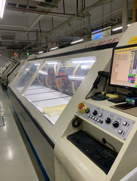
A circuit board drilling is just like a common drill, except that it is optimized for drilling holes in the printed circuit board as opposed to drilling holes in other materials such as wood. To make a drill on PCB, the first factory should have the PCB drilling file. The drill file is also commonly referred to as an NC (numerically controlled) drill file in the industry The Excellon drill file defines the hole locations and tool numbers (X & Y coordinates).
PCB drilling File General Requirements:
- All PCB holes are plated through meaning, there will be solder or silver in the PCB hole barrel.
- Must be Excellon format
- Must be ASCII text viewable. Please open with “Word” or “notepad” to verify a numeric list of X & Y coordinates. There should be no strange graphical characters.
- PCB drill file should not contain “G01”, “G54”, or any reference to “D” codes when opened in a text editor. This indicates a Gerber format and is most likely a drill drawing rather than an NC file.
- Properly formatted PCB drill files have sizes separated with “T” codes that indicate tool numbers. (T01, T02, etc)
- A tool report with sizes is necessary if the sizes are not included in the drill file header.
- For Slots or Cutouts (PCB Express only): Fabrication Drawing, NC Drill File, or Gerber file is necessary to define slot/cutout size and/or location. ◦To achieve a plated slot or cutout place the feature on the drill layer and include an outer layer pad at least the size of the slot or cutout. Maximum diameter for a plated feature is 0.250″
To have PCB drilling file, and now we need to know there are two main drilling holes in the circuit board. One is NPTH hole, another is PTH hole. All the holes in the single sided printed circuit board are NPTH hole. That’s because no need for electronic conduction between layers in single sided PCB. It has just one copper foil layer. PTH hole will appear in double sided or multilayer PCB.
