The best way to solder surface mount devices (SMDs) onto printed circuit boards (PCBs) is with a reflow oven, but when that’s not possible, a hot-air station can be successfully used.
Overview
This article will present the basics of soldering SMDs (surface-mount devices) using hot air. The first part will deal with tools and equipment; the second part will demonstrate some techniques for you to consider.
Warning! Hot-air soldering, like all soldering, involves temperatures that may exceed 500ºC, which can burn eyes, skin, furniture, draperies, clothing, etc. Be very careful when soldering; eye protection is especially important. If any of the actions in this article are unclear or seem risky to you, don’t do them. Safety is your first responsibility.
In order to get the most from this article, you should know the basics of hand soldering. You should be familiar with what constitutes a good solder joint, different types of solder that may be used, and a few basic tools common to electronic assembly. The knowledge gained by using a reflow oven is also beneficial.
Tools and Equipment for Hot-Air Soldering
The key piece of equipment for hot-air soldering is, of course, a hot-air rework station. The unit shown in the photo below is the one used by the author; it is available under a variety of brand names and was built in China. Its price is near the bottom of the range, but it seems reasonably well-built and more than adequate for hobbyist use. Professionals will likely use a more expensive station.
As you can see, it includes not only a hot-air soldering station but also a hand soldering station, as well. There is a separate temperature control and digital readout (in Celsius) for each tool; the hot-air station also has a dial for setting air flow volume.
The syringe contains solder paste, which is a mixture of very small solder particles and flux. Pressing on the syringe plunger forces the solder paste through a blunt needle, which is often used to apply solder and flux directly to the PCB pads before placing the surface mount components. Solder paste is also available in small jars, from which the paste may be
transferred to a syringe or applied directly to the PCB using a very small tool to dip in the paste and dab on the pads.
Solder wire is used (with a hand soldering iron) to touch up or clean up joints that are shorted to adjacent pins or joints that are poorly connected.
Isopropyl alcohol is used along with a soft toothbrush, cotton swabs, and/or a cloth to clean the surface of PCBs before soldering and to remove flux residue after soldering. The alcohol shown is almost 100% pure, but a lesser concentration (such as 91% pure) can also be used if additional time is allowed for the residual water to evaporate.
Flux is necessary to obtain good flow and coverage of molten solder. In addition to liquid flux (as shown), flux is also available in a pen-style applicator and in gel form for application with a syringe and blunt needle.
A pair of bent-nose tweezers is useful for handling SMDs; a vacuum pickup tool is another option.
Solder braid is used (with a hand soldering iron) to remove excess solder from component leads, thereby eliminating shorts between pins. Solder braid is available in different widths for various component sizes; both 2.0mm and 3.0mm (shown) are useful.
The Process
The Test Board Area
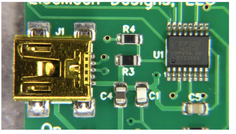
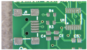
Hot-air soldering is customarily used with surface-mount devices being attached to printed circuit boards. The following descriptions use that method and focus on a small section of a printed circuit board as shown below; the top photo shows a board that has been populated and reflow soldered in an oven, and the bottom photo shows the bare board
As you see, there are only seven component locations shown in the photographs, but the variety will be sufficient to demonstrate basic hot-air soldering techniques: J1 is a mini-USB jack, R3 and R4 are 0805 resistors, C1, C4, and C5 are 0805 capacitors, and U1 is a TSSOP16 USB-to-UART converter.
Solder Paste Choice and Application
Solder paste is available in a variety of mixtures of metal, but the easiest to use is approximately 60% tin and 40% lead. That is the configuration used in the pictures and videos in this article, and is highly recommended. If you have experience with and are comfortable using other solder types (lead-free, for example), feel free to use them—but you will need to make adjustments to the process defined herein.
After thoroughly cleaning the bare PCB with alcohol, the next step is solder application. For the hobbyist, there are two primary methods of applying solder paste to a PCB for surface mount devices: by hand with a syringe or a very small spatula (think wooden toothpick) and by hand with a stencil.
The photo immediately below shows our test board with solder paste that was applied with a syringe. In the case of the 0805 components, a dab of paste was applied to each pad, but in the case of smaller pads, a strip of paste was applied across the pads. (As will become more evident during the reflow process, there is too much paste on every pad.)
The needles for dispensing solder paste are sized by gauge, with smaller numbers representing smaller needles. Those potentially suitable for solder paste application are from 14 through 20 gauge. The author prefers 16 gauge; anything larger dispenses too much solder and anything smaller is very hard to force the solder through. Hopefully, you will produce better results than those shown above.
Some “fill” needle examples are shown in the following photo; the sizes are coded by the color of the plastic connector, but the color code varies from one supplier to another. Note that the tips of the needles may be cut square or at an angle; the author prefers square tips.
SMD Parts Placement
The parts have been placed in their respective places in the two following photographs. An obvious advantage of the board with the stencil-applied paste is that the exact location of the pads is more apparent, which results in more accurate component placement. A not-so-obvious advantage of the syringe-applied paste is that the extra paste holds the parts more securely prior to soldering.
Actual Hot-Air Soldering
In this article, there is a discussion of solder reflow profiles, which might be of interest to you. It describes the four stages of reflow soldering and provides the times and temperatures for each of the four stages when using a soldering reflow oven. The four stages are: pre-heating, soaking, reflowing, and cooling. From a wide perspective, these are applicable to reflow soldering with a hot-air station.
The problem is that there are more variables in play when using a hot-air station than when using a reflow oven. In addition to time and temperature, a handheld hot-air gun involves several other factors, including the size of the nozzle, how far the nozzle is held from the solder, the angle of the airflow from the nozzle to the solder, the speed of the air coming from the nozzle, the speed at which the nozzle is moved around over the areas to be soldered, and probably more factors not recounted here.
Ideally, the gun should be held so that the nozzle opening is perpendicular to the surface of the PCB and approximately 12mm (0.5″) above it. Care should be taken to aim the nozzle toward the pins/pads being soldered while avoiding the bodies of the components as much as possible. Movement of the nozzle should be at as even a pace as possible; however, larger pins/pads (such as those for the mounting feet of J1) will require more hot air time than smaller pins/pads, and so the nozzle will need to be moved over them more often. Generally, it is worthwhile to mentally separate larger PCBs into smaller sections, and completely solder one section before moving to the next. Experience will help to perfect these techniques.
As a result of all these variables, hot-air soldering becomes very personalized—each person develops their own combination of variables that seems to work best for them. At the risk of alienating all the “scientific” readers, the term “style” comes to mind.
The two videos that follow show the author soldering the two variants of the test board section previously shown: one on which the solder paste was applied with a syringe and the other on which it was applied with a stencil. Except for that difference, the techniques and conditions used were intended to be identical; in both cases, the temperature was set to 280°C, the air flow was set to 3, and the 8mm nozzle was used.
Alas, vagaries still crept in, some of which could be blamed on the difficulty of working a few centimeters under a camera lens and around three light stands and a tripod. Nevertheless, there were unintentional differences in actions; watch the two videos and take note of the differences.
Soldering Syringe-Pasted PCB:
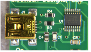
The photo immediately below shows the results of the job done on the syringe-pasted board. All the pads show too much solder, but only two components are adversely affected. J1 has the top two or three pins bridged. U1 has pins 4, 5, and 6 bridged. Pins 9 and 10 are possibly not connected to the pads, and pins 11, 12, 13, and 14 are possibly bridged. Rework will definitely be required and probably will be tedious.
Syringe-pasted board
The next photo shows the results of the job done on the stencil-pasted board. C1 was bumped during the soldering process but was pulled during the reflow process closer to its intended position. C5, which was also bumped, was pulled during reflow fully back where it belonged. J1 stayed in position despite being bumped, thanks to the plastic pins that protrude from the bottom of the jack through holes in the board. And U1 has no solder bridges or other functional problems despite being slightly out of position.
For the sake of appearances, C1 should be moved to be on its pads—but even as is, there are no solder problems that would cause a functional failure.
Stencil Pasted Soldered PCB
Rework of the Syringe-Pasted Board
Rework is a part of surface mount device soldering, and it was absolutely needed on the syringe-pasted board. An attempt was made to clean the solder bridges from U1 with copper braid, but was not successful. As a result, U1 was removed as shown in the following video.
Removal of Old U1:
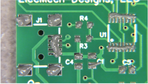
After the removal of U1, the pads were cleared of solder with copper braid and the area was cleaned of flux residue with isopropyl alcohol. Note that the shiny area between pins 10 and 11 of U1 is not solder residue, but is a PCB trace that was too short to be covered by the solder mask. In addition, the solder bridges between the top three pins of J1 were cleared with copper braid before the two photos below were taken.
Old U1 Removed Pads Cleaned
Conclusions
With a little practice, hot-air soldering is not particularly difficult, but each person must find the balance of temperature, air flow, nozzle size, and gun movement that works for them. Clearly, better solder paste application reduces rework, which is a huge time saver. Stencils are usually faster and consistently more accurate for solder paste application than syringes and blunt needles.
Hot-air is superior for removing or repositioning SMD packages (especially multi-pin ICs) but doesn’t come close to the ease of use and speed of a reflow oven. That’s the reason they are called “hot-air rework stations.”