Special attention must be paid to PCB design and manufacturing to meet the demands of 5G era applications and beyond. Issues related to PCB size and thickness, reliable vias, accurate registration, reliable and accurate manufacturing methods, signal integrity, and effective raw materials must be addressed beginning in the design phase and throughout manufacturing.
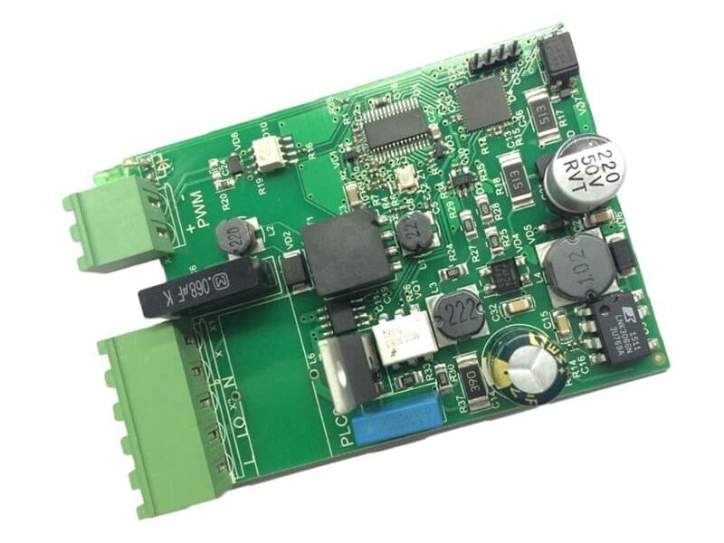
One effective solution to the requirements of 5G technology is the use of HLC PCB boards, such as the one shown in Figure 1, that integrate key features such as skip vias, POVF manufacturing, advanced raw materials, and impedance control.
PCB Changes in the Era of 5G
5G involves a much more advanced integration of components such as antennas. This, in turn, leads to a demand for reduced component size to better support integration. In addition, antennas now require high-frequency materials and strict RF trace tolerance.
Furthermore, the transmission power of 5G base stations is considerably higher than that of 4G, requiring solutions that can achieve reduced losses and excellent thermal management while still supporting high speed, high-frequency solutions with reliable signal integrity.
Another way of looking at the challenges involving 5G technology would be to focus on three key performance characteristics that PCBs must provide:
High speeds
Fast transmission rates
Reduced losses.
PCBs have been found by engineers as an excellent approach to meeting the demanding requirements of 5G technology. PCBs already support size constraints as well as manufacturing methods that include accurate registration and reliable vias. However, engineers have also discovered that they can provide enhanced signal integrity and enhanced impedance control as well as implement raw high frequency and low-loss materials.
Impedance Control
When high-frequency signals are propagating on PCB signal traces, which is often the case in 5G applications, those signals essentially turn the traces into transmission lines. Each point on the signal trace has a particular impedance, and when there is a difference in impedance going from one point to another, distortion of the signal can occur. To preserve signal integrity, PCBs must be designed with impedance control.
Upgraded Raw Materials
Because of the high data rates involved, upgraded raw materials are also necessary. These include high-speed materials such as TU862, a halogen-free composite of epoxy resin, and E-glass fabric. This is considered a mid-loss material and is commonly used with 14 layer PCBs.
Another example is S7439, which can be used with 10 layer PCBs and is considered a low-loss material. M6G is an example of a very low loss material, while M8 is considered an ultra-low loss material. For applications that require high-frequency materials, there are hydrocarbon-based options such as Aerowave 300 and PTFE-based options such as Rogers TC350.
Kinwong Solutions: A Source for 5G HLC PCB solutions
Kinwong Solutions manufactures high-performance HLC PCB solutions for 5G challenges with high layer count (24, 32, and 40) boards.
Kinwong offers boards that:
Implements skip vias with POVF
Have a low registration tolerance of 5mil
Have a back-drill stub length between 2 mil and 10 mil
Achieve trace width/spacing tolerance of ±20% with ±10% for signal trace areas by special control and impedance control
Have very low insertion losses with impedance tolerance of ±8%
The PCBs are available in a selection of high-speed materials, including ultra-low/very low/low/mid-loss materials and high-frequency materials. Additional options include embedded capacitor (except for 24 layer), resistor, or embedded copper coin. Finally, these HLC PCBs are also available as HDI PCBs and optical modules.